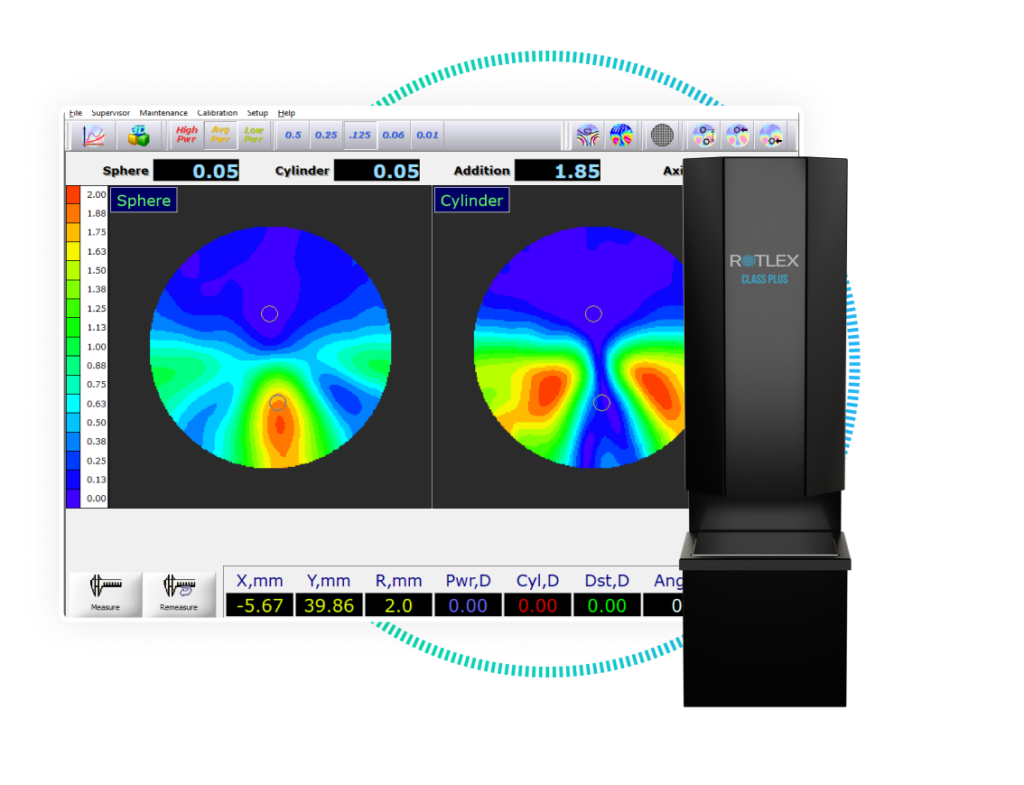

Each Class Plus mapping operation produces two maps – one for the power and the second for astigmatism.
The local values of power and astigmatism can be realized using the color at each point, and matching it to a numerical value according to the scale at the side of each map.In general, there are two classes of parameters affecting the quality of a given lens, design-related and production-related. Listed below is a description of these parameters as well as a method for assigning numerical values to some of them.
When it comes to design issues, one has to bear in mind that the design may be specifically chosen for a patient due to his/her special needs. This makes designers (or knowledgeable subscribers) prefer, or enhance some features of the lens, on the expense of other features which are less required for other types of patients. This makes it impossible to classify a lens as good or bad without understanding patient needs. It is Rotlex policy not be involved in grading designs. However, we can provide the evaluation tools and some guidelines. Using these parameters for evaluating the quality of lenses should be performed by Class Plus users according to criteria and weights of their own choice.
Design-related
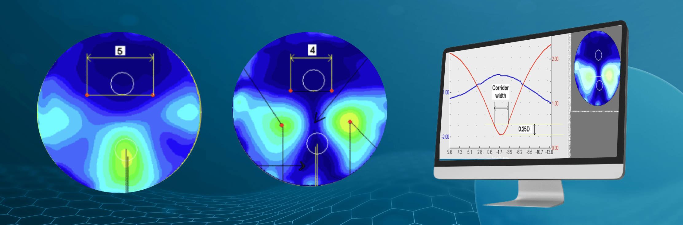
- How symmetric is the design of the lens. This can be calculated from the astigmatism map by the formula: Cyl1– Cyl2, where 1 & 2 refer to the maximum values of the “cheeks” shown in the astigmatism map below. Good designs have Symmetry parameters of less than 0.05D.
- Astigmatism Level. The amount of astigmatism compared to the addition of the lens. This dimensionless parameter is given by the expression: |Cyl1 + Cyl2 | / (2 × Add.). A reasonable number for good designs would be 0.95-1.05 (lower is better!). Back-progressive designs have a value < 0.65.
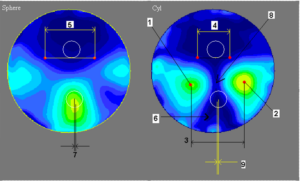
- Astigmatism Field. The symmetry parameter above may be low, but the two “cheeks” may be to close thus narrowing the area having reasonable astigmatism value. Hence, it’s useful to define an Astigmatism Field parameter by the distance 3, marked in the map below.
- Far Vision Field. The horizontal length of the area with both cylinder and power, differing from prescription value by less than 0.25D. Distances 4 and 5 in the maps below demonstrate this concept. However, the shortest between the two should be taken for each direction (left and right). This parameter may also be production-related, rather than pure design-related.
Production-related
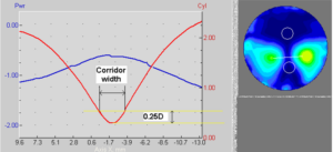
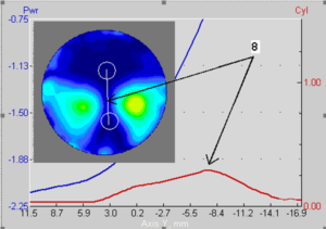
- Corridor quality. One of the most common imperfections is a blocked corridor. Such an example can be seen in the cross-section 1 and astigmatism map below (point 8). It’s not unusual to see values of 0.25D as the highest astigmatism value along the corridor.
- Corridor width. The width is defined as the horizontal distance between two points having a cylinder value 0.25D larger than the cylinder value at the corridor center (See cross-section 2). Such a width can be defined for each vertical position along the corridor, but our Corridor width parameter is the narrowest of them.
- Near-vision positioning. The horizontal distance between the center of the near-vision circle, and the point of maximum power (7 in Power map), or the center of the corridor at this vertical location (9 in astigmatism map). Shifts may be due to printing error but may also be production-related. It’s also important to check the distance between horizontal locations of max power and corridor center, although they are observed on two different maps.
- Near-vision uniformity. Cylinder extensions at the bottom to the astigmatism map are quite common. Point 6 in the map below is a typical example. One needs to verify that such an extension does not come too close to the near-vision circle.
- Far-vision uniformity. This may also be design related as some designs have aberrations narrowing the area to the sides of the far-vision circle. However, it’s also not unusual to have “islands” of power or cylinder differing than the prescription numbers.